The energy question is the main driving force of technical development. This is especially true for the iron and steel industry, where energy sources such as steam, gas and electricity are used on a large scale. With the possibility of using surplus blast furnace gases through the large gas engine, the end of the steam age in the iron and steel industry seemed to have come at the end of the 19th century. Just as the steam engine had played a key role in the "Industrial Revolution", the large-scale gas engine played a predominant role in supplying energy to the iron and steelworks for more than half a century. In the years between 1890 and 1900, only one-fifth of blast furnace gas continued to be used in the smelting industry.
The general introduction and widespread use of large gas engines, one of the most important and revolutionary innovations in the iron and steel industry in the first third of the 20th century, was the temporary culmination of a technological development that had begun in the middle of the 19th century. The large gas engine was a further development of the gas engine, in the research and construction of which Hugo Junkers of the Berlin-Anhaltinische Maschinenbau AG in Dessau played a decisive role.
On the following pages you can learn more about the construction and operation of the gas engine centre and its importance for Maxhütte, whose energetic heart it was for many years of its active operation.
The Construction
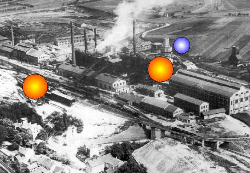
In 1921, the supervisory board decided to expand Maximilianshütte Unterwellenborn into a mixed operation. The construction of the industrial power plant Gasmaschinenzentrale in accordance with the conditions in the area surrounding the Maxhütte and for the expected volume of production became an important part of the expansion measures. With the construction of the gas machine centre, the blast furnace blast furnace gas produced as a by-product was to be used cost-effectively for energy generation.
On 2 November 1921 the 3 MAN machines for the blast furnace wind supply and on 28 November the 4 Thyssen machines for the steelworks wind supply and electrical power generation were ordered. At this time, gas engine construction was in full bloom in Germany. The large gas machines developed by Hans Richter were used to drive piston compressors and generators in both the chemical industry and in iron and steel works. Their development and construction are an expression of high engineering and craftsmanship.
The documents state that construction of the machine hall began in January 1922. Right at the beginning of the construction work, a siding was laid to the works railway network.
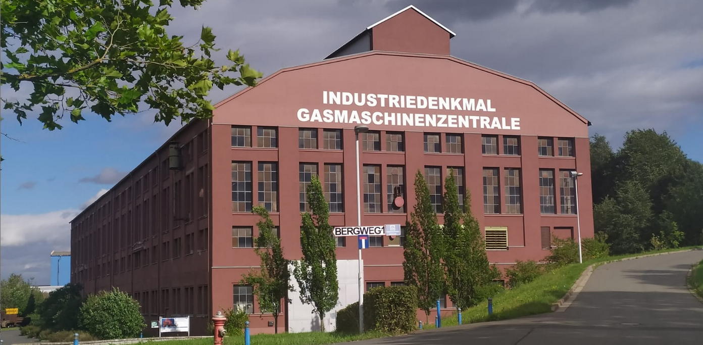
One year later, the shell was completed and in October 1923, at the time of the highest inflation in Germany, the roof was covered with framed concrete elements. The machine hall was built as a cantilevered skeleton structure by craftsmen from the region. At that time it was 95 metres long and 33 metres wide. From 1948 to 1950, it was extended to 121 metres on the west side. In order to be able to support the high dead weight of the machines (Dynamo III, for example, 315 t) and the high loads caused by the expansion forces, the foundations had to be built far into the ground. The nacelle ceiling was erected between the foundations at the operating height of the machines. The assembly was carried out with the 40 t crane of the MAN company.
Due to sales difficulties with the metallurgical products, there was no money to continue the investments. After an interruption of almost 2 years, work on the construction of the gas machine centre could only be continued in 1926. From this year onwards, the gas purification plant and the switch house were built. In 1928, all 7 large gas machines were installed. The remaining work, however, continued until 1929.
The most important technical data of the seven large gas machines (according to their installation from east to west)
| Designation | Number | Manufacturer | Typ | Working cylinders | Wind cylinders | Hub (mm) | RPM | Power (HP) | Wind pressure (atü) | Wind quantity (Nm³/h) | Weight (t) |
| Gas blower blast furnace | 3 | MAN | DTG 12 | 1000 | 2350 | 1200 | 90 | 1310 | 0,6 | 50000 | 318 |
| Gas blower steel mill | 1 | Thyssen | DTG 14 | 1330 | 2100 | 1400 | 85 | 3100 | 2,5 | 50000 | 400 |
| Combined gas blower or dynamo | 1 | Thyssen Siemens-Schuckert | DTG 14 | 1330 | 2100 | 1400 | 85 or 94 | 3100 | 2,5 | 50000 | 402 |
| Gas dynamo | 2 | Thyssen Siemens-Schuckert | DT 14 | 1330 | - | 1400 | 94 | 3600 | - | 2000 kW Generator power | 315 |
The Company
Seven large gas engines worked on the 4-stroke principle.
The 2 cylinders are double-acting and are in tandem arrangement. The gas-air mixture is ignited by special ignition devices that generate an electric arc. The waste heat from the machines was used in waste heat boilers located in the south annex.
The 3 MAN blowers fed a waste heat boiler and each Thyssen gas engine had its own waste heat boiler. The steam they produced was sufficient to supply a 1 MW condensing turbine located on the south side.
In the 1930s and early 1940s, essentially all 3 MAN blowers were run to supply wind to the blast furnaces, 1 Thyssen gas blower to supply glass wind to the Thomas steelworks and 2 Thyssen gas dynamos to generate electrical power (approx. 2 MW each). Initially, the gas dyna- mos fed into the external grid, later they only fed into the plant grid in isolated operation. The reason for this was frequency problems with fluctuating blast furnace gas conditions.
At that time, the gas machine centre was considered the energy heart of the Maximilianshütte Unterwellenborn. The first department head of the gas machine centre was the engineer Hugo Hoffmann. The names of the first machinists have survived. They were Otto Wiefel, Paul Schalter, Hermann Hoffmann and Otto Bock.
An important part of the gas machine centre was the dry gas cleaning system. At that time it consisted of seven filters that worked according to the Halberg Beth system. The blast furnace gas, which had been roughly pre-cleaned at the blast furnace, was finely purified in filter bags and conveyed into the gas pipeline network by fans. The main consumers were the cowpers of the blast furnaces, the boiler house and the gas engine control centre. A disc gas tank with a capacity of 12,500 Nm³ served as a buffer for the gas pipeline network and as a reserve in case of malfunctions.
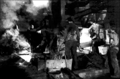
Accidents due to CO gas poisoning occurred time and again in the gas engine control centre. Therefore, precise work and a high level of attention were vital. Apart from CO gas, the working conditions in the gas plant were characterised by noise, heat and sometimes heavy physical work.
Other important plant components of the gas machine centre were:
- the injection water pumping station for cooling the blow moulds at the blast furnaces and the machines in the gas machine centre,
- the switch house with electrical switching equipment and distribution systems.
- the compressor station for the compressed air supply of the Maxhütte,
- a compressed air system 25 atü for starting up the gas machines,
- a gas cooler for the clean gas network to the Kubiersky system gas machine control centre with cooling tower,
- Main pipelines in the works for the following types of energy: cold blast, clean gas, compressed air, blowing blast,
- Blower house at the low-shaft furnace with 3 compressors and 2 blowers, built in the 1950s and 1960s in connection with the operation of the low-shaft furnace.
The Gas Machine Centre after World War Two
After the Maxhütte had been completely shut down by bombing in the last days of the war, production had to be resumed quickly to supply industry in the Soviet occupation zone with pig iron and steel. Only the Maxhütte had 4 blast furnaces for the production of pig iron. On 4 February 1946, blast furnace 2 was started up with an old steam piston blower. With the commissioning of the gas tank and another blast furnace, the energy situation for the gas machine centre returned to normal. The hall was extended to 121 m from 1948 to 1950. This extension provided space for 4 blast furnace turbo blowers and a 1 MW condensing turbine. It also included the west cooling tower.
On 27 November 1950, there was an accident in the gas machine centre. The 48-tonne crankshaft of the gas dynamo 2 broke apart at its predetermined breaking point. A replacement crankshaft was not available. DEMAG Duisburg was unable to supply a new crankshaft at short notice. Employees of the Gas Machine Centre succeeded in producing a replacement crankshaft from 2 defective crankshafts. An achievement that was duly honoured.
In the following years, the machines and plants for the auxiliary energy products blast furnace blast, compressed air, steelworks blast and clean gas production were adapted to the requirements of the operational consumers.
It was necessary to scrap old equipment and build new, modern plants. In the 1950s and 1960s, MAN gas blowers 1 - 3 were dismantled and blast furnace turbo blowers 5 - 8 were built. The higher wind pressure and the greater wind volume were necessary to increase the blast furnace's output. A new control room was built for operation.
The working conditions could be improved considerably. There were also technical changes in the steelworks' wind supply. After the steelwork blowers 1 and 2 in 1951 and 1952, the modern steelwork blower 3 was put into operation in 1968. The Thyssen gas blowers 1 and 2 could then be scrapped. They had become very susceptible to faults and no longer met the requirements of a modern glass plant.
With the commissioning of the floor-blowing oxygen converters in 1974, the turbo blowers 1 to 3 also became obsolete. Of the 7 gas machines, only gas dynamos 2 and 3 remained, which were only run alternately. Since there was not enough space for expansion measures, gas dynamo 2 also had to be scrapped.
The compressed air supply was systematically concentrated with new machines on the free foundations of the dismantled gas machines. Compressors 21 and 22 (still TR-series) were joined by 5 angular compressors 2SL3K 250c. From 1986 onwards, 2 turbocompressors for the solid fuel converter process were put into operation for cooling purposes.
In the 1980s, a converter plant was built to supply heat to the newly built residential area of Saalfeld-Gorndorf, for which blast furnace turbo blowers 1 and 2 had to make way.
 2 Bombentreffer und Bordwaffenbeschuß legen die Maxhütte am 9. April 1945 still.
 Hochofen II wurde 1946 als erster Hochofen in der gesamten Ostzone wieder angeblasen.


